They were to a couple of opposed piston engines. One at www.ecomotors.com and one at www.pattakon.com I got to thinking about ways to make things more symmetrical and ended up visiting the Wikipedia page for opposed piston engines. This led me to the Wikipedia page for free piston engines which led me to the Free Piston Power pack of Pempek Systems. Having recently seen the Ecomotors and PatOP designs, the poppet valves on the Pempek design looked ugly, so I drew this:
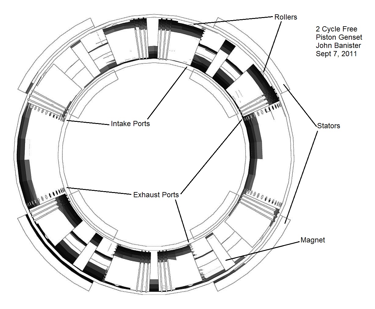
The drawing is very crude, and it's missing stuff, but it gives the general idea. Simultaneous explosions at top and bottom alternate with simultaneous explosions at left and right. I drew the ports symmetrically, but the exhaust ports should open first. I didn't draw the fuel injection apparatus or the intake and exhaust manifolds or the water cooling around the cylinder liner. I chose without a good reason to make the ratio of the mean radius to height of the torus to be 3:1. I chose a bore:stroke ratio for each side to be 1:1.25 after looking at ratios of some marine diesel engines. I arbitrarily chose that the gap separating piston heads at the top of the stroke would correspond to 2 degrees of angle at the center of the torus. Based on these choices, I calculated a piston length of 64 degrees of angle at the center of the torus. I think the cylinder liner where the explosions happen should be a steel wet liner. The wall of the "crankcase" part of the cylinder where the magnet rides should be of some ceramic material that doesn't impede the magnetism. I imagine that the shaft connecting the piston ends is hollow, and lubricant is injected into the top of the magnet disc when the piston stops to change direction and then is subject to inertial pumping as the piston accelerates. I imagine it would be useful to have a proximity sensing strip along the inside of the stator that can determine the position and speed of the magnet (and hence, the piston). I imagine one would need an electrically assisted turbocharger like the one Ecomotors makes and also an electric water pump, lube oil pump and electric radiator fans. I expect the best use for the electricity would be to pass it through a full wave rectifier and make DC to charge a battery, especially if two engines were operated out of phase with one another. It might be better to use some of the electricity generated by the second torus to boost compression pressure on the first (& vice versa) rather than making the pistons heavy enough for inertia to do that job after the pressure on the driving side drops to zero from the exhaust ports being opened. I think the power to weight ratio should be good, although the volume occupied by the torii wouldn't be so small as with some engines. Sometimes I imagine piezoelectric generation at the supports for the pistion rollers powering little electro magnets and getting a little more energy out of the centrifugal aspect of the angular acceleration of the pistons. That might not be worth the effort, though. My dad thinks that the pistons will tend to pivot on the rollers too much, necessitating rollers along the inner wall of the torus as well. Spark plugs work poorly with opposed piston designs, but I like propane, so I imagine injecting propane just after the pistons pass both ports, in homogeneous charge compression ignition (HCCI) mode, and then injecting diethyl ether to improve and control the timing of ignition after more compression has taken place.